Difference between revisions of "Access control and monitoring"
Jump to navigation
Jump to search
| (19 intermediate revisions by 4 users not shown) | |||
| Line 1: | Line 1: | ||
{{Template:Draftworkinprogress}} | |||
= Access Control and Monitoring System Information = | |||
= Access Control = | |||
== Specification == | |||
Spec needs defining. | |||
Paul has some ideas for a door control system. | == Description == | ||
* We want some sort of system to capture an RFID identifier, store it, associate it with a person (in such a way that we can later tie it into some sort of presently-non-existent membership database). | |||
* It needs to interface with the door, which has some sort of radio remote control, and I guess we also need some lock/unlock buttons in the space itself to stop people manually driving the door lock (as it then becomes out of sync with itself). | |||
* With a magnetic close sensor so that when the door is in the closed position it always relocks, but with an override (for Monday nights, for example) | |||
* A very detailed spec for Lancester University is available for inspiration here: https://www.lancaster.ac.uk/iss/info/supplierdocs/network/LU-Access-Control-Spec-v1c.pdf | |||
* A comparison of hackspace access control systems and membership databases can be found here: | |||
** https://docs.google.com/spreadsheets/d/1uXn9LGBIBuJOoRjbfS0Xc9NzUc3StWwt04M8qqtpET8/edit#gid=61365518 | |||
** and | |||
** https://wiki.hackerspaces.org/Hackerspace_Software | |||
* Paul has some ideas for a door control system. | |||
[[File: | == Diagrams == | ||
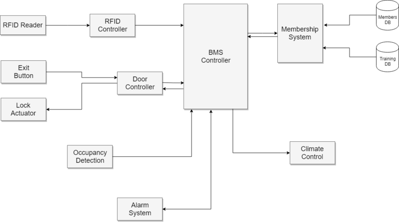
[[:File: | [[File:HH access control.png|none|800px| Hitchin Hackspace Access Control System Block Diagram]] | ||
== Photos == | |||
[[File:2023-01-24 22.38.40.jpg|none|500px|thumb|Front panel of the control box, with a button and an override key]] | |||
[[File:2023-01-24 22.38.52.jpg|none|500px|thumb|Inside of front panel, showing wiring]] | |||
[[File:2023-01-24 22.38.55.jpg|none|500px|thumb|Inside of control panel, with RFID reader at bottom, ESP-RFID control board bottom right, 433MHz interface for lock bottom far right, Arduino door/lock control board top right]] | |||
[[File:2023-01-24 22.39.05.jpg|none|500px|thumb|Back face of RFID the reader]] | |||
[[File:2023-01-24 22.39.34.jpg|none|500px|thumb|Close up of ESP RFID access control board]] | |||
[[File:2023-01-24 22.39.51.jpg|none|500px|thumb|Close up of Arduino door/lock control board]] | |||
[[File:2023-01-24 22.40.00.jpg|none|500px|thumb|Close up of DESI 433MHz lock interface Module]] | |||
== Door Sensors == | |||
=== Door Closed Sensor === | |||
* The door closed sensor is a reed switch activated by a magnet. | |||
* It's connected to a four core cable, with red and yellow wires used for the contacts. | |||
=== Bolt Lock Sensor === | |||
* The lock bolt sensor is a PR12-4DN inductive sensor. | |||
* It needs 10V-30VDC on the brown wire, ground on the blue wire and the black wire is an NPN output. | |||
* Source: https://www.amazon.co.uk/PR12-4DN-Inductive-Proximity-DC10-30V-Equipment/dp/B08QCT5JQV/ | |||
== RFID Reader Module == | |||
The RFID Reader connections are: | |||
{| class="wikitable" | |||
|+RFID Connections | |||
|- | |||
! Function | |||
! Wire Colour | |||
|- | |||
|VCC Supply +12V | |||
|Red | |||
|- | |||
| GND | |||
|Black | |||
|- | |||
| D0 | |||
|Green | |||
|- | |||
| D1 | |||
|White | |||
|- | |||
| Beep | |||
|Yellow | |||
|- | |||
| LED | |||
|Blue | |||
|- | |||
| GND / WG34 | |||
|Purple | |||
|} | |||
= Access Control Database Server System = | |||
[[Category:Bancroft]] | |||
[[Category:Hackspace Build]] | |||
[[Category:Projects]] | |||
Latest revision as of 23:35, 30 April 2023
| DRAFT INSTRUCTION - WORK IN PROGRESS |
Access Control and Monitoring System Information
Access Control
Specification
Spec needs defining.
Description
- We want some sort of system to capture an RFID identifier, store it, associate it with a person (in such a way that we can later tie it into some sort of presently-non-existent membership database).
- It needs to interface with the door, which has some sort of radio remote control, and I guess we also need some lock/unlock buttons in the space itself to stop people manually driving the door lock (as it then becomes out of sync with itself).
- With a magnetic close sensor so that when the door is in the closed position it always relocks, but with an override (for Monday nights, for example)
- A very detailed spec for Lancester University is available for inspiration here: https://www.lancaster.ac.uk/iss/info/supplierdocs/network/LU-Access-Control-Spec-v1c.pdf
- A comparison of hackspace access control systems and membership databases can be found here:
- Paul has some ideas for a door control system.
Diagrams

Photos


Door Sensors
Door Closed Sensor
- The door closed sensor is a reed switch activated by a magnet.
- It's connected to a four core cable, with red and yellow wires used for the contacts.
Bolt Lock Sensor
- The lock bolt sensor is a PR12-4DN inductive sensor.
- It needs 10V-30VDC on the brown wire, ground on the blue wire and the black wire is an NPN output.
- Source: https://www.amazon.co.uk/PR12-4DN-Inductive-Proximity-DC10-30V-Equipment/dp/B08QCT5JQV/
RFID Reader Module
The RFID Reader connections are:
| Function | Wire Colour |
|---|---|
| VCC Supply +12V | Red |
| GND | Black |
| D0 | Green |
| D1 | White |
| Beep | Yellow |
| LED | Blue |
| GND / WG34 | Purple |